The Challenge
Validate and characterize Gas Spring models under development at Nakata Automotiva. Gas spring is a pressurized tubular device, where the piston is constantly pressed by a gas inside the tube.
Such devices are used in rear covers, front hoods of automotive vehicles, also acting in the adjustment of seats.
Or in the agricultural line, in tractors, harvesters, side and/or maintenance covers, as shown in the images below:

Faced with the challenge, the solution must be flexible enough to adapt to any spring inserted in the machine and be able to perform measurements and identify key points in the compression stroke of the machine to score points of interest.
Solution Overview
The product aims to improve the performance of Nakata Automotiva's test and validation routines for “Gas Spring” products, through automated routines and instant analysis with the possibility of generating reports.
The machine in its first version will carry out the expansion tests measuring: displacement and speed in relation to time. Generating instantaneous and average velocity analysis of the Mola-Gás course.
After the analysis, the user will be presented with the options to save the spring settings, as well as the results obtained in configuration file format, with user-readable data and TDMS file to be accessed in comparison software installed on the operators' computer.
The product is designed to run on Windows 10 IoT operating system.
Summary
As mentioned above, gas springs are pressurized tubular devices, where the piston is constantly pressed by a gas inside the tube.
It can be of two types primarily: Hydraulic or Dynamic.
Hydraulic gas spring:
Hydraulic Springs have two types of material for pressurization: gas and oil, which can be filled in equal parts of each, or according to the application, for example: 60% gas and 40% oil.
Dynamic gas spring:
Dynamic Springs have a single type of material for pressurization: gas.
The challenge was solved using a machine that will compress the springs and analyze their speed during decompression.
Consisting of: two-port body, upper divided into fixed and mobile, and lower single and mobile, potentiometric ruler for position adjustment, hydraulic actuator that moves the ruler, and set of claws that lock the springs for compression.
For the measurement system, a NI CompactDAQ was used with digital input and output modules for controlling and activating sensors and analog measurement modules for position control.
For the operator interaction system, the HMI (human-machine interface) was used a TPC from Advantech.
Machine Operation
The machine's working principle is to allow the user to compress it from the dimensions of a gas spring and allow it to expand to measure its expansion speed.
The 4 main mechanical components involved in this process are: fixed top gantry, movable top gantry, potentiometric ruler, movable bottom gantry and grips.
As shown in the image below:

Green arrow we have the fixed upper portico
Blue arrow we have the mobile lower portico
Yellow arrow we have the movable upper portico
By the orange circles we have the claws
Red circle hydraulic actuator and potentiometric ruler
Given the main mechanical components, the machine has a very simple operation:
1st step: Based on the size of the spring to be tested, the jaws close and the lower movable gantry will adjust to the length of the MG in relation to the fixed upper gantry, once this is done, the fitting is performed.
2nd step: After the fitting is carried out, the potentiometric ruler together with the hydraulic actuator will compress the MG.
3rd step: After the compression, the jaws are opened and the gas spring expands with its own force, and the measuring system is activated.
Positioning, compression and return system
The positioning of the spring, both for fitting inside the machine and for compression and return to the fitting point depends on 3 factors:
Distance between the upper and lower portico
Open spring length in mm
Compression stroke
The length variable and stroke are data provided by the operator. Given the 3 variables mentioned above, the machine will first adjust to the open gas spring stroke, so that it can be fitted.
After carrying out this operation, the system proceeds to compression, once the compression is made, the spring will be released to expand naturally, activating the speed measurement system.
After the expansion, the system must return to the docking system. All position referencing is based on the diagram below:

Based on the image above, we can explain that: when receiving the spring characteristics through the operator's HMI, the spring will check its current position, and based on the height of the upper fixed gantry, it will adjust to the fitting position, that is, it will activate the actuator and will feed the system with the positions until it reaches the desired position.
The same applies to compression, with the difference that now the system will only add the current position of the ruler to the compression stroke.
Return will work similarly to snap placement.
Analysis, calculations and graphs
During the validation process of a gas spring prototype, its velocities are calculated in relation to the expansion stroke, as follows:
Dynamic GS Calculation:
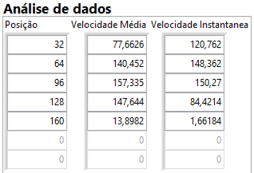
The dynamic GS will have its stroke divided into X amount of speeds, for example a 160mm travel spring will be divided into 5 speeds, that is, its stroke will be divided into 5 points: 32mm, 64mm, 96mm, 128mm and 160mm.
And the average speed and instantaneous speed will be calculated at those points. The results are presented as shown below:

That is, given the position, the software will calculate the average speed at the intervals indicated by the operator and the instantaneous speed at specific points.
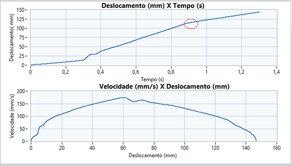
The behavior graph is given by the image below:

Hydraulic GS Calculation:
The hydraulic MG will always have its stroke divided into two: pneumatic and oil and the division is always made when transitioning between these means.
Looking at the graph in the two images, this concept becomes clearer:

And the transition point is the point circled in red.
That is, after capturing the change point from gas to oil, the software will calculate the average speed in both media, returning the results below:

Results:
Using National Instruments technology with LabVIEW and NI Compact DAQ, Blue Eyes Systems was able to prototype a fully customized system for the customer and ensured a scalable and modular system, thus reducing test time and results taking, facilitating quality analysis. and report generation.
References:
[1] National Instruments Corporation, Managing Software Engineering in LabVIEWᵀᴹ Course Manual, Austin, Texas, 2009.
[2] National Instruments Corporation, LabVIEWᵀᴹ Core 3 Course Manual, Austin, Texas, 2014.
[3] DORF, R.C.; BISHOP, R.H.; "Modern Control Systems", Prentice Hall, 10th edition, 2001.

Comments